-
HW-CMM Connectors/HW-M80 Connectors Micron-D Connectors
-
Rectangle Electrical Connectors
-
MIL-DTL-38999 I&II&III&IV D38999 Series Military Circular Connectors
-
MIL-DTL-26482 I &II MS26482 Series Bayonet Circular Connectors
-
Fiber Optic Connector
-
Russian Standard Series Connector
-
Circular Electric Connector Y Series
-
HSB Series High Density Connector
-
FQ Series Waterproof Circular Connectors
-
Custom Connectors ODM& OEM
-
Connector Spare Parts
-
 Steve JobsWish your company better and better!
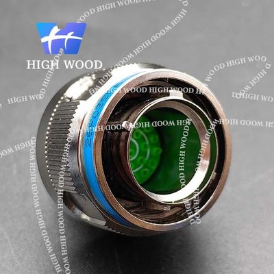
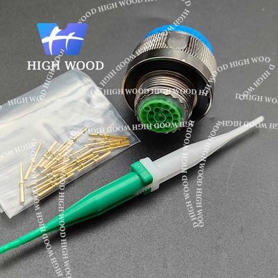
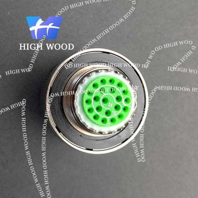
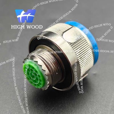
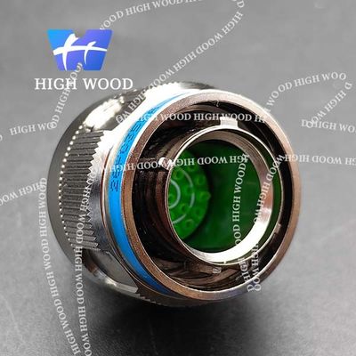
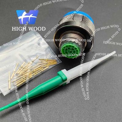
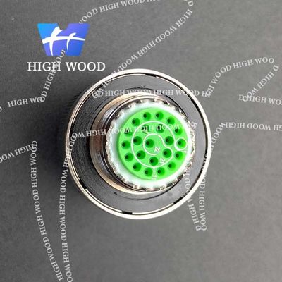
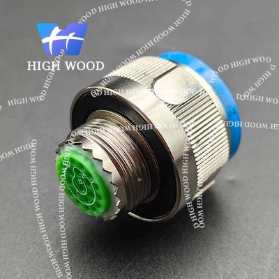
MIL-DTL-38999 Series Ⅲ Connectors, D38999/26FC35PA Circular Electric Connector
| Type Of Connector | Shielding Plug | Contact | Copper Alloy With Gold Plated |
|---|---|---|---|
| Plating | Olive Green Cadmium Plating | Type Of Contact | Crimp Pin |
| Insulator | Thermo-set Plastic | Endurance | 500 Cycles |
| Highlight | MIL-DTL-38999 Series III connector,D38999 military circular connector,D38999/26FC35PA electric connector |
||
D38999/26FC35PA
This series of round connectors, compliant with MIL-DTL-38999 III series requirements, adopt Triple-start threaded quick connection, with an anti-loose mechanism, featuring small size, light weight, high-density contacts, EMI/RFI shielding, removable crimp contacts, and anti oblique-mating;
This product has a fireproof shell, a variety of coatings, and vibration performance of high strength under high temperature, suitable for use in harsh sandstorm and damp circumstances.the material of shell is optional in aluminum-alloy, naval brass, stainless steel or composite.
How to order:
| D38999/ | 20 | W | B | 35 | P | N |
| Basic series | ||||||
| Type of connector 20 = Square flange receptacle 24 = Jam nut receptacle 26 = Shielding plug |
||||||
| Finish W = Olive green cadmium plating F = Electroless nickel plating T = Marine Bronze (copper aluminium alloy) K = Stainless steel passivated L = Black anodized J = Composite material + W M = Composite material + F |
||||||
| Shell size 09 (A), 11 (B), 13 (C), 15 (D), 17 (E), 19 (F), 21 (G), 23 (H), 25 (J) |
||||||
| Contact layout (See below) | ||||||
| Type of contact P = Crimp pin S = Crimp socket PL = Long PCB pin PC = Short PCB pin SL = Long PCB socket SC = Short PCB socket |
||||||
| Orientation N = Normal A, B, C, D = Alternative |
||||||
Product pictures:
![]()
![]()
![]()
![]()
Shell size:
| Shell No. | A (max) | B Thread | C (max) |
| 09 | 31.00 | M12*1-6g | 21.80 |
| 11 | 31.00 | M15*1-6g | 25.00 |
| 13 | 31.00 | M18*1-6g | 29.40 |
| 15 | 31.00 | M22*1-6g | 32.40 |
| 17 | 31.00 | M25*1-6g | 35.60 |
| 19 | 31.00 | M28*1-6g | 38.50 |
| 21 | 31.00 | M31*1-6g | 41.70 |
| 23 | 31.00 | M34*1-6g | 44.90 |
| 25 | 31.00 | M37*1-6g | 48.00 |
Electrical:
Contact resistance and current rating:
| Contact ID | Diameter (mm) | Resistance (mΩ) | Current (A) |
| 22D# | Φ 0.76 | ≤ 12.0 | 5.0 |
| 20# | Φ 1.00 | ≤ 5.0 | 7.5 |
| 16# | Φ 1.60 | ≤ 2.5 | 13.0 |
| 12# | Φ 2.40 | ≤ 1.5 | 23.0 |
| 10# | Φ 3.15 | ≤ 1.0 | 40.0 |
EMI shielding:
At 1GHz: minimum attenuation 85dB (F and W) At 10GHz: minimum attenuation 65dB (F)
At 10GHz: minimum attenuation 50dB (W)
Withstanding voltage (V):
| Service rating | M | I | II | N |
| Sea level | 1300 | 1800 | 2300 | 1000 |
| 21000m | 800 | 1000 | 1000 | 600 |
Insulation resistance:
Normal ≥ 5000 MΩ, damp heat ≥ 100 MΩ Electrical continuity between shells:
W class ≤ 2.5 mΩ, F class ≤ 1.0 mΩ, K class ≤ 5.0 mΩ


